HDD Pre-Planning: Mitigating Subsurface Utility Risks
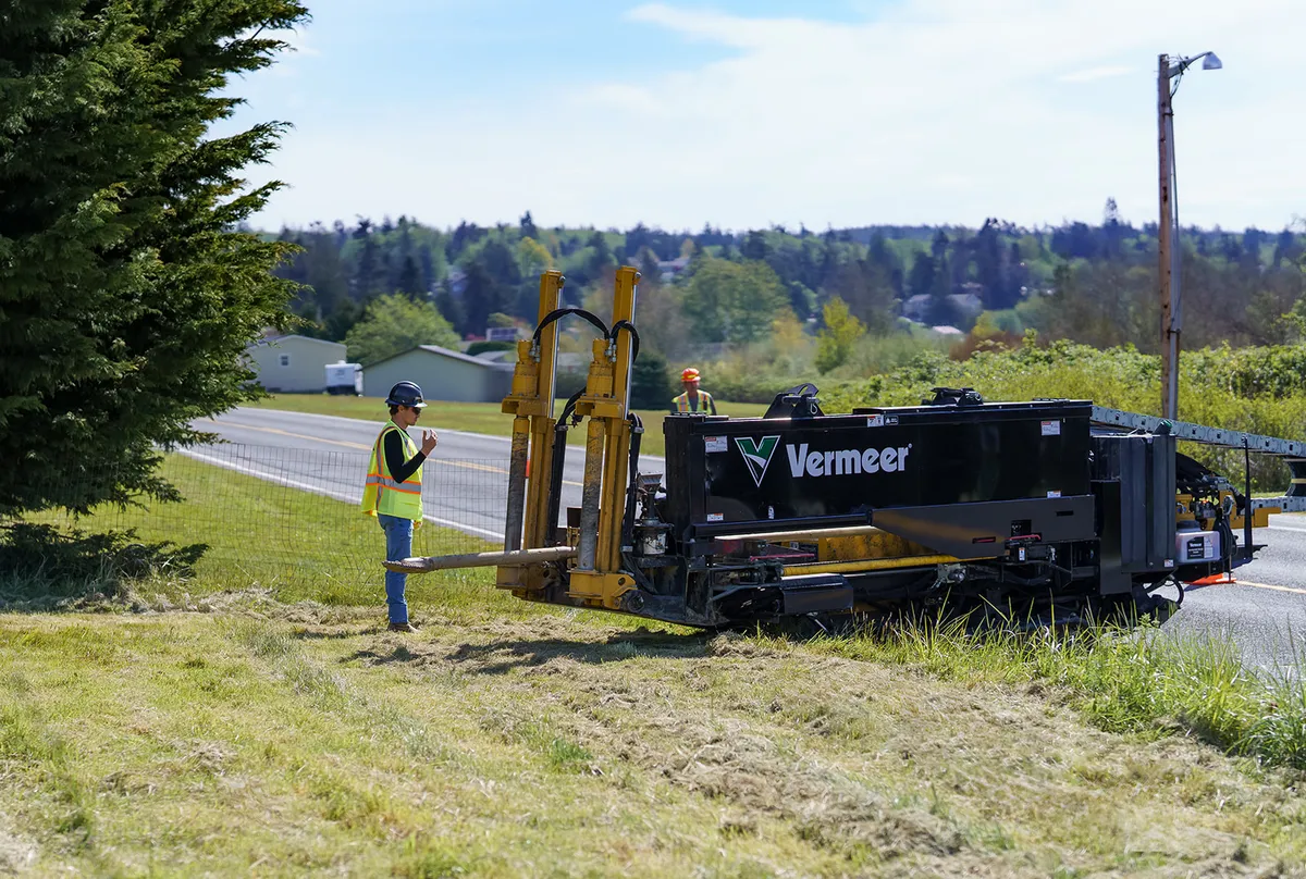
Horizontal Directional Drilling (HDD) is a highly efficient trenchless method for installing utilities, but its successful execution depends entirely on rigorous pre-planning. Underground spaces are increasingly congested with legacy fiber, water, gas, and high-voltage lines, making strikes a major hazard.
At Merra, we utilize Subsurface Utility Engineering (SUE) protocols to verify and map these existing lines. SUE represents a branch of civil engineering defined by ASCE 38-02 standards that structures utility data into four Quality Levels. Quality Level D (QL-D) involves collecting existing utility records, while Quality Level C (QL-C) surveys visible above-ground features such as utility pedestals, fire hydrants, and vault boxes. Quality Level B (QL-B) applies surface geophysics, including electromagnetic induction (EMI) and ground-penetrating radar (GPR), to determine the horizontal position of buried utility segments. Finally, Quality Level A (QL-A) provides absolute 3D precision by physically exposing the utility through non-destructive vacuum excavation (potholing), documenting its exact depth, size, and material.
Geological bore samples are also analyzed to assess soil conditions, water tables, and potential collapse risks. The geotechnical investigation determines the Standard Penetration Test (SPT) N-values and classifies the soil profile under the Unified Soil Classification System (USCS). In loose, sandy soils (cohesionless formations), drilling fluid design must focus on creating a filter cake to hold the borehole walls together and prevent fluid loss. In heavy, swelling clay formations, polymer additives are introduced to inhibit water absorption and prevent clay from swelling and sticking to the drill string. When encountering solid rock, such as volcanic basalt common in the Pacific Northwest, our teams deploy mud motors and specialized tri-cone roller bits to cut the path efficiently.
Calculating the maximum allowable drilling fluid pressure—using cavity expansion models such as the Delft equation—is critical to prevent hydraulic fracturing of the soil, commonly known as a frac-out. If fluid pressures exceed the shear strength of the overlying soil, drilling mud can escape through fractures to the surface or into protected waterways, causing environmental damage and halting construction.
By combining SUE mapping and geological data into a 3D drilling profile, we can systematically eliminate subsurface conflicts before our rigs start turning. The finished bore plan calculates the minimum bend radius (MBR) for the High-Density Polyethylene (HDPE) or Steel conduits to be pulled through the hole. Ensuring that the entry and exit angles (typically 8 to 15 degrees) and curves do not over-stress the pipeline prevents structural failures, ensuring a highly resilient and compliant utility corridor.
Related Resources
Next-Gen Fiber Deployment: Overcoming Dense Urban Barriers
Key techniques and structural methodologies for deploying fiber backbone systems in highly populated urban grids with minimal community disruption.
Utility Undergrounding: Long-term Grid Resilience
Why municipalities are actively converting aerial power and telecom networks to underground vaults, and the financial & safety returns of grid hardening.